We use cookies on our website to ensure you get the best possible experience – they allow us to tailor content specifically to you, analyse our website to help make improvements, and display ads that are applicable to you across other websites. If you’re happy with this, please select “Allow all", or personalise the cookies you allow with “Manage”. Clicking on “Reject non-essential” will remove these cookies, but the site may not function to its best abilities. For more information, please visit our cookie policy
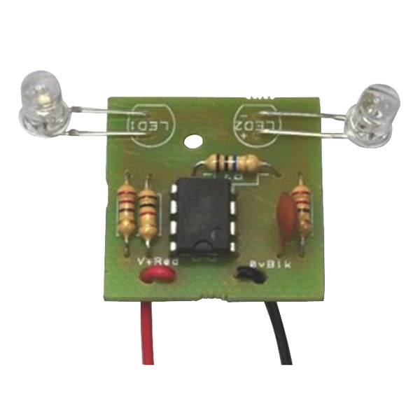
A kit of parts to make a simple and reliable alternating flasher circuit based around possibly the most famous 'chip' of all, the 555 timer.
In this circuit, it is used as an astable (oscillator) and directly drives two LEDs, flashing them alternately.
The kit is quick to build, even by absolute beginners. It provides a quick way to add some electronic interest to a variety of projects, from aliens with flashing eyes through to edge-lit acrylic display stands.
Kit contains printed circuit board and standard components
See Technical Specification table for list of kit contents
Click here to download constructional notes for this kit
Q. Hi. Is it possible to vary the frequency with a variable resistor. If so how would I go about it? Thanks, Oliver.
A. Hi Oliver, thank you for your question. Yes the R2 and R3 can be changed to suit the flash rate, so it can be changed to suit. The full data sheet can be found here.
Q. Hi I've build a model truck and have 3mm leds fitted,I'm looking for some sort of flasher unit to work 8 bulbs so they flash at the same time like indicates on a car.
Many thank
A. Hi Mark, thank you for your question. These can be used 3 LEDs per I.C. Please see the data sheet.