
Q. The LIS3DH chip has two interrupt outputs, which of the interrupt outputs is connected to the INT pad of the board?
A. Hi Jim, thank you for your question. The schematic diagram can be found on page 27 of this document.

| Qty | Was | Unit Price (Ex VAT) |
|---|---|---|
| 1+ | £6.04 | £5.47 |
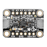
The Adafruit LIS3DH Triple-Axis Accelerometer is a neat 3-axis accelerometer with adjustable sensitivity and a choice of either I2C or SPI bus connectivity. Select from ±2, 4, 8 or 16g sensitivity; ±2g gives a higher resolution for slow movements while ±16g is best for high speed tracking. It can be configured to detect a single tap and free-fall, either of which can be configured to toggle an external interrupt pin to signal your microcontroller. As a bonus the board has 3 x analogue inputs with 10-bit resolution and you can read the values from the chip's on board registers.
Supplied as a fully assembled and tested accelerometer board plus a strip of 0.1in. pitch header pins for you to solder on as required. Adafruit provide a free tutorial to help get you started.
*Customers looking to resell on eBay or Amazon should contact Adafruit directly.
| Type | Accelerometer |
|---|
Q. The LIS3DH chip has two interrupt outputs, which of the interrupt outputs is connected to the INT pad of the board?
A. Hi Jim, thank you for your question. The schematic diagram can be found on page 27 of this document.