Industry Schools FE/HE Site: Industry Site: Schools Site: FE/HE Site: Mobile
  • Suggested Queries


Velleman MK102 Flashing LEDs Kit

Order Code:  

70-4138

  Copy to clipboard
Brand: Velleman  Copy to clipboard MPN: MK102  Copy to clipboard GTIN-14: 05410329001025
  • Country of Origin: Hong Kong
 Report an error

Discontinued

A simple multivibrator circuit driving two LEDs.


  • Suitable for many applications including model construction and education
  • Adjustable flashing speed with two potentiometers
  • Power consumption approx. 8mA
  • Dimensions: 30 x 35 x 15mm
  • Kit contains all components required including printed circuit board and construction instructions
  • Velleman MK102

Requires 1x PP3 battery (not included).

Please note: This is a self-assembly kit and requires soldering.

Type LED display
Ready Assembled? No

Questions


*Question functionality currently disabled


20 November 2016 Question by: Rapid Customer | Product code: 70-4138
Q. Hi, do these come fully prepared and ready for use as per your photo and will they fit in a dummy alarm bell box to make it look active,many thanks Jase.
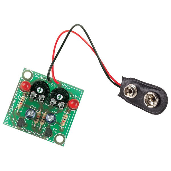
A. Hi Jase, thank you for your question. This kit does not come assembled and will require building a very simple kit to build but a soldering iron and basic tools would be required.


03 December 2015 Question by: Rapid Customer | Product code: 70-4138
Q. Will the components work with a 12v dc supply instead of 9v?
A. Hi Blueshift, thank you for your question. 9V is the maximum.


22 March 2012 Question by: Rapid Customer | Product code: 70-4138
Q. Can I get this and un-solder the LED's and put in different LED's that will be on a length of wire so that this can be tucked hidden away on my project.
A. Hi Chris, thanks for your question. This can be done on that project, as long as the LEDs you replace are as close to the same value the original were.


21 October 2011 Question by: Rapid Customer | Product code: 70-4138
Q. Can the lights flash rate be adjusted independantly?
A. Hi Peter, thank you for your question. If you look at the circuit diagram on the data sheet https://www.rapidonline.com/pdf/70-4138.pdf the variable resistors are used to influenec the charge /discharge rate of the capacitors C1 & C2 – which in turn load the bases of the transistors- which act as switches for the LEDs. They therefore affect the time interval between the leds flashing – so in a manner of speaking they do control each one – but they are dependant on each other – you cannot adjust one without affecting the other.

Reviews


Be the first to submit a review